Cen-Tech multimeters are versatile tools for electrical DIY, offering seven functions like resistance measurement, crucial for troubleshooting and circuit analysis.
What is a Cen-Tech Multimeter?
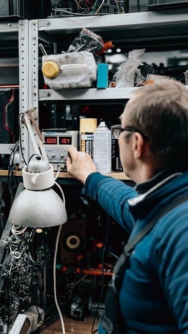
Cen-Tech multimeters, widely available, are digital instruments designed for measuring various electrical characteristics. They are essential tools for both professional electricians and hobbyists tackling electrical projects. These multimeters can measure voltage (AC & DC up to 750V/1000V), current (up to 200mA), and resistance (up to 2000K Ohms).
Beyond basic measurements, many Cen-Tech models offer diode testing and transistor testing (hFE) capabilities. Understanding a multimeter’s functions can initially seem overwhelming, but mastering resistance measurement is particularly vital for DIY electrical work. Different models exist, such as the Cen-Tech 57015 and the Digital Clamp-On Multimeter (Model 66897/95652), each with specific features detailed in their respective manuals.
Safety Precautions
Prioritize safety when using a Cen-Tech multimeter. Never attempt to measure voltage on circuits exceeding 750V AC or 1,000V DC, and do not test current beyond 200mA. Always turn off the multimeter before switching between functions to prevent damage and ensure accurate readings.
Avoid touching exposed metal leads during measurements to prevent electrical shock. Consult the transistor manual for proper orientation when performing transistor tests. Never measure resistance on a live circuit – ensure power is disconnected. Remember, improper use can be hazardous; familiarize yourself with the manual before operation. Proper lead storage is also important for maintaining safety and functionality.
Understanding the Multimeter Components
Essential components include test leads, ports (COM, VΩmA), a range selector switch, and a display – each playing a vital role in accurate measurements.
Test Leads and Ports (COM, VΩmA)
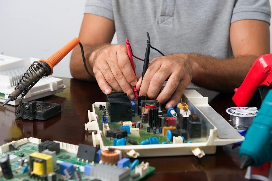
Test leads are fundamental for connecting the multimeter to the circuit under test; Always ensure a secure connection to obtain reliable readings. The COM (Common) port is universally the black lead connection, serving as the reference point for measurements. The VΩmA port, typically red, handles voltage, resistance, and low current measurements.
Carefully plug the black lead into the COM jack and the red lead into the VΩmA jack before initiating any tests. Avoid touching the exposed metal conductors of the test leads during measurements to prevent inaccurate readings or potential shock hazards. Proper lead placement is critical for safe and effective multimeter operation. Store leads with the multimeter when not in use.
Range Selector Switch
The Range Selector Switch is central to operating the Cen-Tech multimeter, dictating the type and scale of measurement. Before any test, carefully rotate the switch to the appropriate function – voltage (AC/DC), current, resistance, diode, or transistor testing (hFE).
Initially, start with a higher range setting and gradually decrease it until a precise reading is achieved. This prevents damage to the meter from overloads. Remember to turn off the multimeter before switching functions to avoid inaccurate results or potential damage. Understanding the switch’s positions is key to utilizing the multimeter’s full capabilities and ensuring accurate measurements.
Display Overview
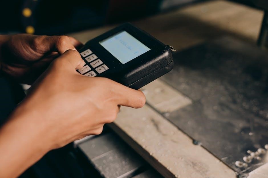
The Cen-Tech multimeter’s display is your window into electrical measurements. It typically features a digital readout showing the measured value, along with units (Volts, Amps, Ohms). Pay attention to indicators for DC voltage, AC voltage, and potential overload conditions.
Some models include a low battery indicator, alerting you when replacement is needed. The display’s clarity is crucial for accurate readings; ensure good lighting and a stable viewing angle. Familiarize yourself with the display’s symbols and their meanings to interpret measurements correctly and avoid misdiagnosis during electrical work.
Basic Measurements
Cen-Tech multimeters excel at fundamental measurements: voltage (AC/DC up to 750V/1000V), current (up to 200mA), and resistance (up to 2000K Ohms).
Voltage Measurement (AC & DC ― up to 750V AC/1000V DC)
Measuring voltage with your Cen-Tech multimeter requires careful attention to safety and proper setup. Always begin by ensuring the Range Selector Switch is positioned to the appropriate voltage setting – either AC or DC. Never exceed the meter’s maximum ratings of 750V AC or 1000V DC. Connect the black test lead to the COM port and the red test lead to the VΩmA port.
To measure DC voltage, connect the leads in parallel with the component or circuit you’re testing, observing polarity (red to positive, black to negative). For AC voltage, polarity doesn’t matter. Read the voltage displayed on the screen, and if the reading is low, select a more sensitive range on the Range Selector Switch for greater accuracy. Remember to turn off the multimeter before changing functions.
Current Measurement (up to 200mA)
Measuring current demands extra caution, as it requires breaking the circuit. Never attempt to measure current on a circuit exceeding 200mA, as this could damage the multimeter and pose a safety risk. First, turn off power to the circuit. Connect the black test lead to the COM port. Crucially, the red test lead must now be connected to the mA port (separate from the VΩmA port) for current measurements.
Break the circuit and insert the multimeter in series – the current must flow through the meter. Turn the Range Selector Switch to the appropriate mA range. Restore power and observe the current reading. Remember to turn off power and disconnect the meter before changing functions or ranges.
Resistance Measurement (up to 2000K Ohms)
Measuring resistance is vital for electrical DIY tasks, but always ensure the circuit is de-energized. WARNING: Never measure resistance on a live circuit! Connect the black test lead to the COM port and the red test lead to the VΩmA port. Turn the Range Selector Switch to the desired resistance range, starting with the highest setting (2000KΩ) and decreasing as needed for a more precise reading.
Touch the test lead tips to the component or circuit points you wish to measure. Read the displayed value. If the reading is ‘1’ or ‘OL’, increase the range setting. Mastering resistance measurement unlocks crucial troubleshooting capabilities.
Advanced Measurements & Functions
Cen-Tech multimeters offer diode and transistor testing, including hFE settings for NPN identification, expanding diagnostic capabilities beyond basic voltage and resistance checks.
Diode Testing
Diode testing with a Cen-Tech multimeter verifies the functionality of diodes by checking for a voltage drop. Begin by dialing the multimeter to the diode symbol. Connect the black test lead to the COM port and the red test lead to the VΩmA port.
Next, connect the red lead to the anode (positive side) and the black lead to the cathode (negative side) of the diode. A proper functioning diode will display a voltage drop, typically between 0.5V and 0.8V.
If the reading is “OL” or infinite, the diode is likely open. A reading of 0V indicates a shorted diode. Reversing the leads should show “OL” as well; if not, the diode is faulty. This test confirms if a diode is allowing current to flow in the correct direction.
Transistor Testing (hFE setting, NPN identification)
Transistor testing on a Cen-Tech multimeter utilizes the hFE setting to determine the transistor’s current gain. First, set up the multimeter to the hFE position. Understanding transistor pin configurations is vital; consult the transistor’s datasheet for proper identification.
Insert the transistor leads into the appropriate test sockets – typically Base, Collector, and Emitter. The multimeter will display a value representing the hFE (DC current gain).
Identifying NPN transistors is crucial. A reading indicates an NPN transistor, while no reading or a different result suggests a PNP type. Compare the obtained reading with the transistor’s specifications to assess its functionality and health.
Specific Cen-Tech Models & Manuals
Comprehensive manuals are available for specific Cen-Tech models like the 57015 and the Digital Clamp-On Multimeter (66897/95652), detailing operation and safety.
Cen-Tech 57015 Manual Information
The Cen-Tech 57015 manual provides detailed instructions for operating this popular digital multimeter. It covers essential aspects, beginning with safety precautions – emphasizing never exceeding 750V AC or 1000V DC, and limiting current tests to 200mA.
The manual guides users through connecting the test leads correctly (black to COM, red to VΩmA), and explains the function of the Range Selector Switch. It details how to perform basic measurements like voltage (AC & DC), current, and resistance (up to 2000K Ohms).
Furthermore, the Cen-Tech 57015 manual illustrates advanced functions such as diode testing and transistor testing (using the hFE setting to identify NPN transistors). Always consult the transistor’s datasheet for proper comparison of readings.
Cen-Tech Digital Clamp-On Multimeter (Model 66897/95652)
The Cen-Tech Digital Clamp-On Multimeter (models 66897/95652) offers a comprehensive set of features detailed in its instruction manual. This manual emphasizes safety, reiterating voltage limits of 750V AC and 1000V DC, and current limits of 200mA.
It provides a product overview and guides users through setup, operation, and maintenance; Correct lead connection is crucial: black to COM, red to VΩmA. The manual explains how to utilize the clamp function for non-contact current measurement, a key advantage of this model.
Troubleshooting sections address common issues, and the manual details proper storage of leads with the multimeter to ensure longevity and accuracy of measurements.

Troubleshooting Common Issues
Common problems include no display reading or incorrect values; consult the manual for solutions, ensuring proper lead connections and range selector settings.
No Reading on Display
If the Cen-Tech multimeter displays no reading, several factors could be at play. First, verify the battery is functioning correctly and properly installed; a weak battery is a frequent cause. Next, ensure the test leads are securely connected to both the multimeter and the circuit being tested. Confirm the Range Selector Switch is set to an appropriate position for the measurement you’re attempting – it shouldn’t be on an ‘off’ setting or a completely incompatible range.
Inspect the test leads themselves for any breaks or damage in the wiring. A faulty lead will prevent a complete circuit. Finally, double-check that you are attempting to measure a valid parameter (voltage, current, or resistance) and that the multimeter is configured for that specific function. If issues persist, consult the comprehensive instruction manual for detailed troubleshooting steps specific to your Cen-Tech model.
Incorrect Readings
Experiencing inaccurate readings with your Cen-Tech multimeter? Begin by confirming the Range Selector Switch is positioned correctly; an improper range can lead to significant errors. Ensure the test leads are firmly connected to both the multimeter’s ports (COM, VΩmA) and the circuit under test. Verify you’re measuring the correct parameter – attempting to measure AC voltage while set to DC, for example, will yield a false result.
Consider potential external influences, such as electromagnetic interference, which can sometimes affect readings. If testing transistors, remember to consult the transistor’s datasheet to compare your multimeter’s hFE reading against the specified values. Always avoid touching the exposed metal tips of the test leads during measurement, as this can alter the circuit and impact accuracy.
Maintenance and Storage
Proper care extends multimeter life. Clean the device regularly and always store the test leads securely with the multimeter when not in use.
Cleaning the Multimeter
Maintaining a clean multimeter ensures accurate readings and prolongs its lifespan. Before any cleaning procedure, always disconnect the test leads and ensure the multimeter is turned off. Use a damp cloth, lightly moistened with water or a mild detergent solution, to wipe down the exterior casing.
Avoid abrasive cleaners or solvents, as these can damage the plastic components or the display. Pay particular attention to the ports where the test leads connect, removing any dust or debris that may accumulate. For stubborn dirt, a soft brush can be used gently.
Never immerse the multimeter in water or any other liquid. Ensure the multimeter is completely dry before reconnecting the test leads and resuming operation. Regular cleaning contributes to reliable performance and prevents potential inaccuracies in measurements.
Lead Storage
Proper storage of your multimeter test leads is essential for maintaining their integrity and ensuring accurate measurements. After each use, inspect the leads for any signs of damage, such as cracks or frayed wires. If damage is detected, replace the leads immediately to avoid potential safety hazards.
To prevent tangling and damage, neatly coil the leads and store them in a dedicated compartment, often found within the multimeter’s carrying case or alongside the unit itself. Leads and store with multimeter is a good practice.
Avoid storing the leads in direct sunlight or extreme temperatures, as this can degrade the insulation. Secure storage protects the leads from physical damage and maintains their conductivity, guaranteeing reliable performance over time.